

Object Oriented Analysis (OOA) : Object Oriented Analysis (OOA) is the first technical activity performed as part of object oriented software engineering. OOA introduces new concepts to investigate a problem. It is based in a set of basic principles, which are as follows- The information domain is modeled.
Object Oriented Design (OOD) : An analysis model created using object-oriented analysis is transformed by object-oriented design into a design model that works as a plan for software creation. OOD results in a design having several different levels of modularity i.e., The major system components are partitioned into subsystems (a system-level “modular”), and data their manipulation operations are encapsulated into objects .
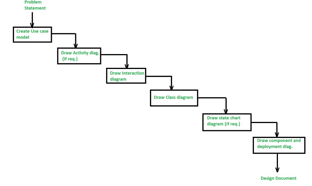
There are various steps/stages in the analysis and design of an object-oriented system as given in below figure :
1. Create a Use case model: The first step in the analysis and design of an object-oriented system is to recognize the actors interlinked with the system. After that, create the use case and draw the use case diagram.
2.Draw activity diagram (If required) :
The activity Diagram demonstrates the dynamic nature of a system by creating the flow of control form activity. An activity addresses a procedure on some class in the framework that outcomes in an adjustment of the condition of the system. The below figure shows the activity graph handling a request to convey a few products.
3.Draw the interaction diagram :
A interaction diagram shows a collaboration, comprising a bunch of articles and their relationship, including the messages that might be dispatched among them. Interaction diagram address the unique perspective on a system.
4.Draw the class diagram :
The class diagram is responsible for showing the relationship between the classes. There are four types of relationships available in class diagrams :
i)Association
It is a semantic connection between classes. At the point when an association associates two classes, each class can send messages to the next in sequence or a collaboration diagram. They may be bi-directional or unidirectional in nature.
ii)Dependencies
They connect two classes and are always unidirectional in nature and display that one class, depends on the definitions of another class.
iii)Aggregations
They are a stronger form of association that shows the relationship between a whole and its parts.
iv)Generalizations
They are used to display an inheritance relationship between the two classes.
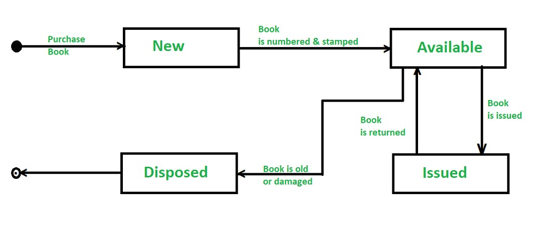
5.Design of State chart diagrams :
A state chart is utilized to show the state space of a given class, the occasion that influences progress starting with one state then onto the next, and the activity that outcome from a state change. A state change graph for a “book” in the library management system is shown below
6.Draw component and development diagram :
These diagrams address the static execution perspective on a system they are identified with class diagrams in that a segment ordinarily guides to at least one class, interface, or coordinated effort.